

Engineering 5 Gbps on a 4-Layer Board: DockFrame's USB 3.0 Backbone
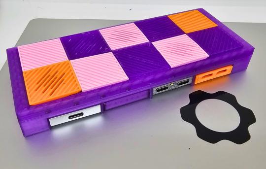
Quick context if you're new here: DockFrame is a modular USB-C dock we're building around the Framework Expansion Card format. You slide in standard Framework cards or our custom Tool Cards (multimeter, power supply, MCU dev board) and your desk setup reconfigures on the fly. One cable to your laptop, everything else snaps in.
But none of that matters if the data path is slow. Nobody wants a modular dock that drops their NVMe enclosure down to USB 2.0 speeds. So from the start, we committed to a real USB 3.0 SuperSpeed backbone: 5 Gbps per port, two downstream expansion slots, proper hub controller architecture.
This post is about what that actually involves on a compact PCB.
The hub architecture
DockFrame has a dedicated USB 3.0 hub controller sitting between your laptop (upstream) and two downstream USB-C ports. Each downstream port does full 5 Gbps SuperSpeed. We also have an ESP32-S3 on the bus for device management, MicroSD storage, and PD negotiation.
So yeah, you can have an NVMe enclosure on port 1 and a capture card on port 2, both running simultaneously at full speed. The Framework Expansion Card slots live on the same backbone, so a Biwin Mini SSD card gets the full SuperSpeed pipe too.
All of this on a 4-layer PCB that has to fit inside the DockFrame enclosure. That's where it gets interesting.
5 Gbps is a geometry problem
USB 2.0 at 480 Mbps is pretty forgiving. Route your traces with some basic care and you're fine. USB 3.0 at 5 Gbps is a completely different game.
The signals run as differential pairs, two traces carrying opposite-phase signals, and they need to hold 90 ohms differential impedance the whole way. If the impedance drifts anywhere along the path, you get reflections. The receiver can't distinguish ones from zeros cleanly, and the link either drops speed or just fails.
Here's the thing: that 90-ohm number comes entirely from physical geometry. Trace width, spacing between P and N lines, distance to the ground reference plane, dielectric constant of the material in between. Change any one variable and the impedance shifts.
Our stackup:
F.Cu  (top)       35 µm copper     ← USB 3.0 routes here
                   0.10 mm prepreg  ← this distance sets the impedance
In1.Cu             35 µm copper     ← GND reference
                   0.40 mm core
In2.Cu             35 µm copper     ← GND / power
                   0.10 mm prepreg
B.Cu  (bottom)     35 µm copper     ← USB 3.0 routes here too
Total thickness: 0.76 mm. Prepreg dielectric constant: 4.5.
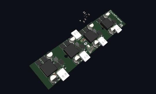
For 90 ohms differential on this specific stackup, the calculation gives us 0.12 mm trace width with 0.10 mm spacing on the outer layers (microstrip). Inner layers are a stripline environment, so there we flip to 0.10 mm traces with 0.12 mm spacing.
You cannot just eyeball these or copy them from another board. More on that in a minute.
Locking it down in KiCAD
We enforce the impedance geometry through KiCAD's custom design rule system. These override whatever you might try to do manually. The editor literally won't let you draw a USB 3.0 trace at the wrong width:
(rule "usb_ss_outer"
    (layer outer)
    (condition "(A.NetClass == 'USB_SS_90OHM')")
    (constraint track_width (opt 0.12mm))
    (constraint diff_pair_gap (opt 0.10mm))
)

(rule "usb_ss_inner"
    (layer inner)
    (condition "(A.NetClass == 'USB_SS_90OHM')")
    (constraint track_width (opt 0.10mm))
    (constraint diff_pair_gap (opt 0.12mm))
)
There's also a 0.20 mm clearance rule between SuperSpeed pairs and anything else on the board. At 5 Gbps on a compact layout, crosstalk is a real problem.
Every USB 3.0 net (upstream TX/RX, downstream port 1 and port 2) gets assigned to the USB_SS_90OHM net class, so the constraints apply automatically across the entire design.
Routing: 12 differential pairs, layer transitions, return paths
Each USB-C port has four differential pairs going to the hub controller: SuperSpeed TX, SuperSpeed RX, and USB 2.0 D+/D- for backward compatibility. Upstream port mirrors that. That's 12 differential pairs minimum, all needing impedance control and length matching.
Some of these routes have to change layers. The trace starts on F.Cu, drops through a via to B.Cu, and continues to the destination. Every via is an impedance bump. We're using 0.4 mm vias with 0.1 mm drill, and we place ground return vias right next to each signal via. Without the return via, the ground current has to find its own way across the layer transition and you get a nice little antenna right where you don't want one.
What we learned from our reference design
We're building in public, so we're going to share this one even though it's a little embarrassing.
We have a production board, the Jetson Orin Baseboard (8 layers), that runs USB 3.0 SuperSpeed without issues. When we started DockFrame, we pulled the trace geometry straight from that design. Same width, same gap. These are proven values from a board we manufacture and sell.
During our signal integrity review, we found that the values we'd copied were actually the net class defaults, placeholder numbers that the Orin board never used for actual routing. The real impedance-controlled geometry was in a separate design rule file that overrode those defaults at route time. We'd grabbed the wrong numbers.
And it gets better: even the correct values from the Orin board wouldn't have worked on DockFrame. Different layer count (8 vs 4), different prepreg thickness (0.12 mm vs 0.10 mm), different dielectric constant (4.3 vs 4.5). Plug the Orin geometry into our stackup and you don't get 90 ohms. Not even close.
We caught it before fabrication, recalculated everything for our stackup, and locked in the correct constraints. Lesson reinforced: impedance geometry is not portable between boards. Different stackup, different answer. Always.
Next steps
Design rules and net class assignments are done. Here's what's left:
▪ Re-route the SuperSpeed pairs with corrected geometry (KiCAD's diff pair router picks up the new constraints automatically)
▪ Length tuning: match P and N traces within each pair. USB 3.0 spec allows less than 5 ps of skew, which is about 0.75 mm of trace length difference
▪ Fab verification: send the stackup to our fabricator so they can run the impedance numbers against their actual material data before we commit to production panels
▪ Test coupons: impedance test structures on the production panel to verify 90 ohms on real hardware
After the USB 3.0 backbone is validated, the next phase is finalizing the Tool Card electrical interface, making sure the Multimeter, Power Supply, and other cards negotiate properly through the hub.
What the community is telling us
We've had close to 400 people sign up on hwlab.io/dockframe so far, and the feedback is shaping what we build. A few things keep coming up.
The most common use case is exactly what you'd expect: people want a USB-C dock that uses the Framework cards they already own. A lot of Framework users have extra Expansion Cards sitting in a drawer. An SD reader they swapped out, a spare USB-A, whatever. DockFrame gives those cards a home where they're actually functional.
But the Tool Cards are what gets people really excited. The multimeter and power supply cards come up constantly. Someone described it as "a space saving modular development aid, easily pull power for microcontrollers with a nice multimeter for in-circuit sanity checks" and honestly that's a better pitch than anything we could write. We've also gotten requests for logic analyzers, GPIO/UART breakout cards, oscilloscope modules, even an SWR analyzer for RF work. One person wants to hook it up to classic car sensors for temperature and oil pressure readings. We love that kind of thinking.
The other thing we hear a lot: people are tired of cheap docks that break or behave unpredictably. One subscriber put it bluntly: "I've burnt through several cheap docks I bought on Amazon so having a reliable upgradable and fixable one is gonna be huge." That tracks with why we're doing the signal integrity work in this post. A modular dock that can't maintain 5 Gbps reliably is just another disposable hub with extra steps.
If you have ideas for Tool Cards or features you'd want to see, leave your feedback here. We read everything.
Why this matters
DockFrame is a modular dock. But under the snap-in convenience, there's real signal integrity work happening. USB 3.0 at 5 Gbps on a 4-layer board in a compact form factor is not trivial. Impedance-controlled differential routing, stackup engineering, fab coordination, it all has to be right.
We're doing this because DockFrame should be fast enough that you never think about speed. Plug in an SSD, get 5 Gbps. Plug in a capture card, clean video. Snap in a Framework USB-A card, works exactly like it does in your laptop.
That's the bar.
DockFrame is a modular USB-C hub for Framework laptop users, makers, and engineers. Open source hardware, open process. Follow us on GitHub, join the Discord, or tell us what you want to see.
Support Us on Crowd Supply
We’re on Crowd Supply, and we need your help to bring DockFrame to more people. Your backing makes it possible to keep prices low and quality high, so everyone can enjoy the power of an open-source modular USB Hub ecosystem.

Check out the campaign and get involved: DockFrame on Crowd Supply

