
Building a Breadboard in a Framework Expansion Card
If you've been following along you know the DockFrame pitch by now: a modular USB-C dock built around the Framework Expansion Card format, hosting standard Framework cards and our own Tool Cards. The multimeter went first. The power supply went second. This is the third one.
This post is about the BreadBoard Card, the one that turns DockFrame into a development platform. It carries a Seeed Studio XIAO ESP32-C5, exposes the module on standard 2.54 mm sockets, brings out a USB-C downstream port for whatever device you're prototyping against, and gives you protected power on both rails. Three blocks of silicon, a handful of passives, and a question that turned out to be harder than it looked: what does a dev board want to be when you stop thinking of it as a dev board?
The simplest card we've shipped. Not the easiest.
There's no isolated front-end on this one. No programmable buck-boost. No analog telemetry path you have to coax into 1 % accuracy. The schematic fits on three sheets and the BOM has 55 unique parts. By the standards of the multimeter or the power supply, the BreadBoard Card is uncomplicated.
What it has instead is decisions. Where does power come from when the dock is the only host. How do you fail-safe a 5 V rail that feeds whatever someone clipped onto the breadboard. How do you make a USB-C port behave as a downstream port without paying for full PD silicon. How do you socket an MCU module so the next-gen XIAO drops in without redrawing the schematic. Every one of those is a single page of design, but the page matters.
We wanted this card to be the one you reach for when you're not sure yet what you're building.
What's actually on the board
DOCKFRAME HUB  ───►  USB-C plug J3 (Molex 1054440011, mid-mount SMT)
                       │
                       │   D+/D-           CC1 = 5k1 to GND
                       │      │            CC2 = 5k1 to GND     ← advertises as UFP/sink
                       │      ▼
                       │   TPD1E05U06DPY x2   ← ESD on the diff pair
                       │      │
                       │      ▼
                       │   XIAO ESP32-C5 socket  (J1, J2 + 1x11 strips)
                       │      │
                       │      └──► USB 2.0 DD_UPSTREAM+/- to module
                       │
                       ▼
                  VBUS rail
                       │
                       ├─► F3 = 1.35 A PTC fuse  (12H1350C)
                       │      │
                       │      ▼
                       │   U1 = TPS2553DDBVR  ← current-limited switch, 1.65 A trip
                       │      │      │
                       │      │      └─► DS2 (RED) fault LED
                       │      ▼
                       │   /VBUS_Fault_Prot/OUT_PROT  (protected 5 V)
                       │      │
                       │      ├─► J7  USB-C receptacle, downstream port
                       │      └─► J4  aux power header (open question, more later)
                       │
                       └─► U5 = SY8089A1AAC buck  ──► +3V3
                                                       │
                                                       ▼
                                                   U4 = TPS2553DDBVR  ← OCP on the 3.3 V rail too
                                                       │      │
                                                       │      └─► DS3 (RED) fault LED
                                                       ▼
                                                   XIAO 3V3 socket pin + breadboard rails
The first thing worth noticing is that both power rails get a TPS2553 current-limited switch. On a card this size, with breadboard pins exposed to the world, that's not paranoia. A dropped jumper wire across the breadboard rails happens. A wrong-way LED happens. Without an OCP somewhere upstream of the user's hands, every wrong-way connection becomes a host-side fault, which on a dock means everything on the dock notices.
R13 and R18 set the trip points. Both are sized at 15 k, putting the rails at ~1.65 A with the SY8089 buck rated for 2 A. The OCP ordering came out right: the switch trips before the buck does, the fault LED lights, the XIAO gets a chance to complain to the host instead of the host going dark.
The two USB-C ports, doing two different jobs
There are two USB-C connectors on this card, and they're not the same kind of part. J3 is the plug: the male connector on the edge of the card that mates with the DockFrame hub's receptacle. Molex 1054440011, vertical mid-mount SMT, 24 contacts. The CC pins have 5.1 kΩ Rd pulldowns (R6, R7) because the card is a UFP/sink: the hub sources power, the card consumes it. No PD silicon, no negotiation. We get whatever the dock decided to hand us, which on the DockFrame main hub is always a clean 5 V.
J7 is the receptacle: SHOUHAN HC019, the female USB-C port you plug your own devices into. We picked a legacy USB 2.0 passthrough rather than a strict USB-C downstream port. CC1 and CC2 on J7 are intentionally floating. The only data on offer is USB 2.0 D+/D- coming out of the XIAO, so SuperSpeed and SBU lines have nothing to pass through, and a full DFP with Rp pull-ups, role detection, and VCONN handling costs more board area than this card can spare. The trade-off is well understood: USB-A-style devices plugged into J7 enumerate via VBUS presence and work fine. Strictly USB-C-compliant peripherals that refuse to enumerate without seeing a host advertise Rp will not start. That's the bargain.
Cable-flip is still supported: D+ and D- are wired to both A6/B6 and A7/B7, so the diff pair lands on the same XIAO USB pins regardless of orientation.
Why the XIAO sits in a socket
Every other XIAO carrier we've seen solders the module down. That choice saves 0.3 mm of Z-height and trims a tiny bit of BOM cost. It also commits the card to a single MCU family for the rest of its life.
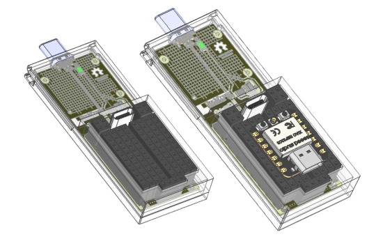
The XIAO ecosystem has thirty-plus modules at this point, all sharing the same 14-pin castellated pad layout, the same 21 × 17.5 mm outline, and the same USB-C port at the top edge. So we put two through-hole socket strips on the card instead of a footprint. Pop in a C5 today, pop in whatever Seeed ships next year, the rest of the BreadBoard Card doesn't know the difference. There's a second benefit nobody asks for until they need it: a module you can pull out of the socket is a module you can recover. Bricked firmware, blown GPIO, supply voltage mishap. Swap, debug on a bench, slot back in.
We used eleven-position 2.54 mm header strips even though the XIAO only fills seven pins per side. The extra four pads on each side are how the carrier exposes the rest of the card to a bread board: protected +5 V, +3V3, GND, and the auxiliary header all land on those breadboard-friendly pins. A jumper from a 2.54 mm header to a solderless breadboard is the cheapest possible bring-up loop.
Eleven modules, one socket
The XIAO lineup at the time of writing covers eleven distinct modules across six silicon vendors. All of them are 21 × 17.5 mm. All of them share the same fourteen castellated pads at 2.54 mm pitch and the same USB-C port at the top edge. Slot any of them into the BreadBoard Card and the rest of the design doesn't notice.
                     core(s)                            radio                              memory             sleep
XIAO SAMD21          Cortex-M0+ @ 48 MHz                none                               32 KB / 256 KB     n/a
XIAO RP2040          dual Cortex-M0+ @ 133 MHz          none                               264 KB / 2 MB ext  n/a
XIAO RP2350          dual Cortex-M33 @ 150 MHz (+ FPU,  none                               520 KB / 2 MB      50 µA
                     switchable to RISC-V Hazard3)
XIAO RA4M1           Cortex-M4 @ 48 MHz (+ FPU)         none                               32 KB / 256 KB     45 µA
XIAO ESP32-C3        RISC-V @ 160 MHz                   Wi-Fi 4 + BLE 5                    400 KB / 4 MB      44 µA
XIAO ESP32-S3 Sense  dual Xtensa LX7 @ 240 MHz          Wi-Fi 4 + BLE 5                    512 KB + 8 MB      26 mA
                                                       (+ OV2640 camera + PDM mic)        PSRAM / 8 MB       active idle
XIAO ESP32-C6        dual RISC-V (160 MHz + 20 MHz LP)  Wi-Fi 6 + BLE 5 + 802.15.4         512 KB / 4 MB      15 µA
XIAO ESP32-C5        single-core RISC-V @ 240 MHz       dual-band Wi-Fi 6 + BLE + 802.15.4 384 KB + 8 MB      see datasheet
                                                                                          PSRAM / 8 MB
XIAO nRF52840 Sense  Cortex-M4F @ 64 MHz                BLE 5 + Thread + Zigbee            256 KB / 1 MB      5 µA
                                                       (+ 6-axis IMU + PDM mic)
XIAO MG24 Sense      Cortex-M33 @ 78 MHz                BLE 5.3 + Thread + Zigbee + Mesh   256 KB / 1.5 MB    1.95 µA
                                                       (+ 6-axis IMU + mic)
XIAO nRF54L15 Sense  Cortex-M33 + RISC-V @ 128 MHz      BLE 6.0 + 802.15.4 (Matter, Zig.)  256 KB / 1.5 MB    see datasheet
                                                       (+ IMU + mic)
The point isn't the chips. It's what each unlocks when the rest of the card is fixed. A handful of projects we've heard people describe, and which XIAO is the right answer for each:
◼ Matter sensor for the room next door. XIAO ESP32-C6 or nRF54L15 Sense for Thread + Matter. MG24 Sense if you want it running on a coin cell at 1.95 µA idle.
◼ QMK or ZMK macropad clipped to the dock. XIAO RP2040 or SAMD21 for QMK. ZMK adds nRF52840 to that list.
◼ TinyML inference rig. XIAO ESP32-S3 Sense. OV2640 camera, PDM microphone, 8 MB PSRAM, Edge Impulse and TensorFlow Lite recipes already published.
◼ 5 GHz Wi-Fi 6 prototyping. XIAO ESP32-C5, which is what this card shipped with. Currently the only ESP32 module in the line with dual-band Wi-Fi 6.
◼ BLE peripheral with a battery in the picture. XIAO nRF54L15 Sense for the newer Nordic radio and BLE 6.0, or nRF52840 Sense for the 5 µA sleep current with on-module IMU.
The software side is just as plural. Arduino, PlatformIO, ESP-IDF, MicroPython, CircuitPython, Rust, TinyGo, and Embedded Swift each work on at least one XIAO module today, several on most of the line. Zephyr supports every current XIAO; FreeRTOS and NuttX cover the bigger ones. None of those toolchains know or care that they're running inside a DockFrame card. The carrier is a power supply with USB on top. Pick the silicon for the project, pick the language for the team, plug it in. The Seeed XIAO topic page is the canonical map of who supports what, and the introduction page has the full comparison table with per-module datasheets, schematics, and KiCad libraries.
One more thing worth saying. The XIAO line is what we designed around, but the socket itself doesn't read part numbers. It's two 2.54 mm strips, eleven positions each, 21 mm apart, and anything that fits that mechanical envelope physically seats. Adafruit's QT Py family was drawn as a XIAO drop-in and works without thinking about it. A lot of small third-party dev boards with 2.54 mm pads and a compatible pinout will fit too. The catch is the wiring: power and USB are routed to the pin positions a XIAO occupies, so a non-XIAO module may need a couple of jumper wires from the breadboard rails to its own supply and USB lines instead of getting both for free at the socket. If the outline and pad layout are roughly XIAO-shaped, it's plug-and-play. If not, you're a jumper or two away.
The C5 is the part that makes this interesting
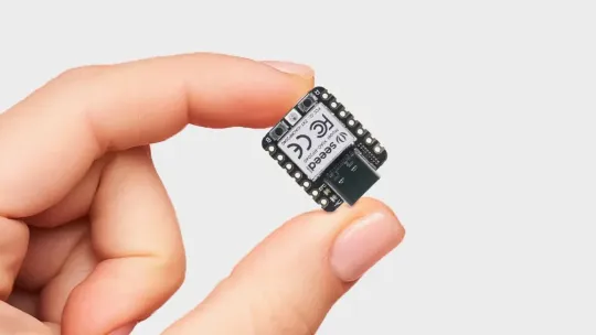
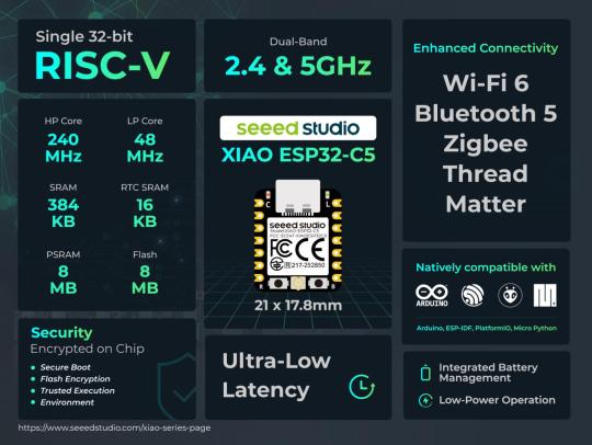
The XIAO ESP32-C5 is, as of this writing, the first ESP32 module with dual-band Wi-Fi 6. 2.4 GHz, 5 GHz, BLE 5.0, and IEEE 802.15.4. One 21 × 17.8 mm module covers Wi-Fi, Bluetooth, Thread, Zigbee, and Matter, on a single-core RISC-V running at 240 MHz, with 384 KB on-chip SRAM, 8 MB of PSRAM, and 8 MB of flash on-module. There's a u.FL footprint for an external antenna, an external one ships in the box, and the bottom of the module breaks out JTAG (MTDO/MTDI/MTCK/MTMS), I²C, SPI, two UARTs, and five ADC channels.
That stack means the BreadBoard Card isn't really an MCU dev board in the 2018 sense. It's a wireless prototyping platform that happens to live in a dock slot. A Matter device under your desk, a Thread border router test rig, a 5 GHz Wi-Fi sniffer for the band that's still mostly empty in residential RF, an AES-128/256 accelerated Secure-Boot-V2 device for product work that needs the cryptographic peripherals to be hardware-backed. None of those fits naturally on a benchtop with USB cables draped to a host. All of them fit naturally as a card slotted into the dock you already have plugged into your laptop.
There's a side benefit that doesn't show up on the headline spec sheet: this is a cheap way in to RISC-V development. The C5 core is a 32-bit RISC-V part, and the ESP-IDF toolchain has had a RISC-V backend in-tree since the ESP32-C3. Anything you can write in C or C++ for an ESP32, you can compile here and end up with actual RV32 instructions in flash instead of Tensilica Xtensa. The esp-rs project supports the C-series in its HAL if you'd rather write Rust on a real RISC-V target. And because the C5 brings JTAG out to pads on the reverse side, an openocd setup gets you single-stepping through your own disassembly on actual silicon, not a simulator. A XIAO ESP32-C5 retails for under $10. There aren't many cheaper paths to spending an evening reading your own RV32 instructions on hardware you can keep using for something else the next morning.
Out of the box, the recommended toolchain is the Arduino IDE with the Espressif ESP32 board package at version 3.3.5 or later, selecting the XIAO_ESP32C5 target. The C5 enumerates as USB CDC through the dock, the standard blink sketch compiles unmodified, and from there you're on the ESP-IDF roadmap (Arduino, IDF, MicroPython, esp-rs, Zephyr) like any other ESP32 in the line. The BreadBoard Card itself is transparent at the firmware layer.
The downside of putting a 2.4 / 5 GHz radio next to a switching buck regulator and a USB hub is the obvious one. We pushed the SY8089 to the bottom edge of the card and put the XIAO socket at the top edge, but the gap is millimeters and the antenna pattern is what it is. PoC measurement will tell us how bad. If the noise floor in the bands we care about is unworkable, the next revision exposes a u.FL pad on the carrier side too and an external antenna lives outside the enclosure.
How you actually use it
Plug the card into the dock. The XIAO enumerates as a USB CDC device through the hub, just like a directly-cabled one would, at 115200 baud. Push code with whatever toolchain you already use. The breadboard-friendly pins on either side of the socket give you protected +5 V, +3V3, GND, and an auxiliary header to wire jumpers from. The BreadBoard Card is invisible at the firmware layer; it's a power harness and a USB conduit with sockets, not a runtime.
What the review process kept catching
The biggest architectural change happened in v5, when the VBUS protection block came out of the root sheet into its own hierarchical sub-sheet, VBUS_Fault_Prot.kicad_sch. Same component count, much cleaner ownership: the PowerSupplies sub-sheet now owns the 3V3 path, VBUS_Fault_Prot owns the 5 V protection, and the root sheet only owns the connectors and the XIAO socket. Three pages, three responsibilities, no orphans.
There's an honest open item: the J4 aux header. The intent is an injection point for external power that bypasses the dock, for running the XIAO off a battery or a different supply for thermal, EMC, or isolation reasons. Right now the connector is on the board, but its common net is wired to itself and nothing else, which makes it a header that does nothing. The right fix is either to route J4 to the buck input as a DC-jack alternative, or to mark the connector DNP and add it back with intent in a future revision. We're discussing which.
Spreadsheets and nitpicking. It's also how the card ended up with a 1.65 A protection trip wired to a switch that actually trips, instead of one that asserts after the upstream buck has already browned out.
What's next
Bench bring-up checklist for the first PoC, in the order we'll run it:
◼ Measure VOUT at J7 with no load. Expect ~5 V. Measure V_DS across U1 at idle, expect under 100 mV.
◼ Measure +3V3 at the XIAO socket with the module idle (~50 mA) and again with Wi-Fi active (~250 mA peak). DS3 must stay off through both.
◼ Short-test J7 VBUS to GND with a bench supply current-limited to 2 A. Confirm U1 trips, DS2 lights, current settles around 1.65 A. Recover after removing the short.
◼ Repeat the short test on the XIAO socket 3V3 to GND. Confirm U4 trips, DS3 lights.
◼ Plug a USB-A flash drive (via adapter) into J7. Confirm it enumerates through to the host. This is the validation gate for the floating-CC decision. Repeat with a strictly USB-C-only peripheral to map where "works without Rp" stops working.
◼ Measure 2.4 GHz and 5 GHz noise floor with the SY8089 active and inactive, antenna in card position.
If the card survives all of that, the BreadBoard Card slots in as Tool Card #3. From there the focus shifts to finishing the Dual USB-C Expansion Card, the sibling already on the bench. Once that one is done, the lineup is what we need to take to Crowdsupply. The crowdfunding campaign is the next milestone DockFrame is heading into, and the BreadBoard Card is one of the cards it ships with.
What the community is telling us
"MCU Dev Card" was the third most-requested Tool Card in the early-access feedback, behind only the multimeter and the power supply. Nineteen of you named it specifically: people building Matter sensors, ham radio operators looking at 802.15.4, students who wanted "an ESP32 that's just there in the dock," and a surprising number of engineers who said they'd already given up on their last solderless breadboard and switched to a Tool Card form factor because the cables were worse than the projects.
A couple of you also asked, reasonably, why we picked the XIAO over a bare ESP32 module footprint. The honest answer is that the XIAO line is the only MCU module family right now with this much breadth, this much continued investment, and a pin-compatibility promise across vendors. Soldering a bare ESP32-C5 footprint would save 0.5 mm of Z-height and lock us to one chip for the next five years. Socketing the XIAO buys a free upgrade path every time Seeed ships a new module.
Why this matters
Most "dev boards" are a USB cable in a box of cables. You set them up on a corner of the desk, connect a couple of jumpers, forget to power them down for a week, and eventually move them so the desk can become a desk again. A Tool Card sized dev board doesn't go through that cycle. It lives in the dock you already use. The cable that powers it is the cable that powers your laptop. The breadboard pins on the side are real, the protected rails are real, and the firmware path is whatever toolchain you brought with you.
We want the BreadBoard Card to be the card you forget is there until you remember you wanted to prototype something. The first PoC is the first real test of whether we hit that bar.
DockFrame is a modular USB-C hub for Framework laptop users, makers, and engineers. Open source hardware, open process. Follow us on GitHub, join the Discord, or tell us what you want to see.
Support Us on Crowd Supply
We’re on Crowd Supply, and we need your help to bring DockFrame to more people. Your backing makes it possible to keep prices low and quality high, so everyone can enjoy the power of an open-source modular USB Hub ecosystem.
Check out the campaign and get involved: DockFrame on Crowd Supply
