
Building a Multimeter in a Framework Expansion Card
If you've been following along, you already know the DockFrame pitch: a modular USB-C dock built around the Framework Expansion Card format, hosting standard Framework cards and our own Tool Cards. Multimeter, power supply, MCU dev board, more on the way.
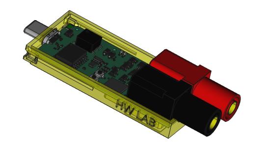
This post is about the first Tool Card we're actually building, the Multimeter, and why fitting one inside a Framework Expansion Card turned out to be a completely different problem than building a multimeter.
A multimeter is easy. This multimeter is not.
Hand any competent EE the task "design a multimeter" and they'll ship one in a few weeks. Input protection, a high-impedance divider, a chopper-stabilized op-amp, an ADC that doesn't embarrass you, some firmware. Textbook design for forty years.
Tell them "design a multimeter that fits inside a Framework Expansion Card, runs over USB, is galvanically isolated from the host, reports readings over WiFi and Bluetooth, and survives a probe touching something it shouldn't" and the problem changes.
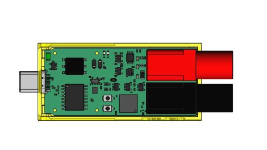
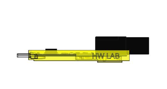
A Framework Expansion Card's usable internal volume is roughly the size of a thumb drive. Everything you want inside, connectors, MCU, isolation barrier, analog front-ends, antenna, banana jacks, power conversion, has to fit in that box. Component choice stops being a performance optimization and turns into a packing problem. You don't pick the lowest-noise op-amp for your budget. You pick the lowest-noise op-amp that also comes in SC70 and costs under a dollar. Your BOM gets filtered through the mechanical CAD before it reaches your schematic editor.
Isolation inside a thumb drive
A multimeter worth shipping has to be galvanically isolated from whatever it's plugged into. If your probes are touching a live circuit and your USB ground is your laptop chassis, you really want a physical barrier between those two worlds. This is the part we refused to compromise on.
Isolation on a benchtop instrument is easy, spread the domains apart, leave a finger's-width gap, drop in a chunky transformer, done. Inside a Framework Expansion Card, every millimetre of creepage and clearance is contested. The solution is a two-domain split running right down the middle of the board:
HOST SIDE                    |   ISOLATED MEASUREMENT SIDE
                             |
USB-C plug                   |   ESP32-S3R8 MCU
  ├─ TPD1E05U06DPY ESD       |     ├─ 16 MiB SPI flash
  ├─ SMAJ7.0CA VBUS TVS      |     ├─ 2.4 GHz PCB antenna
  └─ F1 input fuse           |     └─ 3.3 V rail (SY8089 buck)
                             |
ADuM4160 USB isolator  ──────┤───►  D+/D− crosses here (5 kV rated)
                             |
SN6501 push-pull driver ─────┤───►  Wuerth 750315371 transformer
                             |        ├─ 475 µH, 1:1.1
                             |        └─ Generates isolated secondary rail
                             |
                             |   Measurement AFEs (V, I, L, R, C)
                             |   Banana jacks
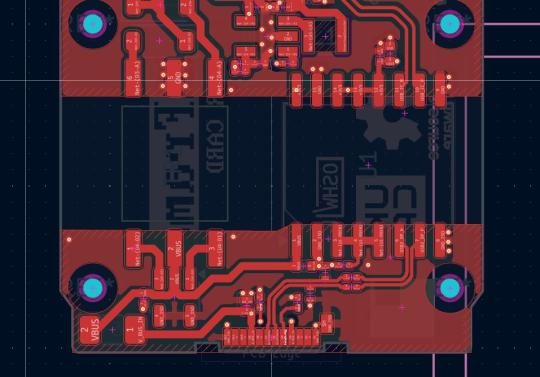
The data pair crosses through an ADuM4160BRWZ, a 5 kV digital USB isolator that speaks full-speed USB on both sides. Power crosses via an SN6501 push-pull driver feeding a Wuerth 750315371 signal transformer, generating the isolated secondary rail. Textbook topology on paper. In this volume the real question is never "will it work", it's "can you place those parts next to each other without violating creepage, and is there any room left once you've done it." We went through three placement passes before the answer was yes.
What's behind the barrier
Five measurement modes, each on its own sheet, each picking whatever architecture fits the board area.
Voltmeter: three-stage resistive divider (10 MΩ → 2 MΩ → 523 kΩ) feeding an OPA388 chopper-stabilized buffer, with a TS5A3359 switch picking the range. Offset trim we don't have to ship is offset trim we don't have to maintain. Ammeter: INA219 across a 0.1 Ω shunt, with a GAQY212 photorelay gating the high-current path, no room for a mechanical relay, and the photorelay is quieter when it switches. Resistance, capacitance, and inductance each get a TS5A3166 range switch and their own front end; the inductance mode uses an LMV331 comparator running a resonant-discharge measurement.
All five modes share a single ADC path through analog muxing. Only one AFE is active at a time. It's a little fragile around mode transitions, but it's the only way to get five modes out of an ADC budget this tight.
A 2.4 GHz antenna next to a 60 V divider
The wireless angle is the part we're least certain about. Might as well say it up front.
We swapped the original RP2040 for the ESP32-S3R8 because we wanted WiFi and BLE telemetry, once you've used a wireless probe on the other side of the bench you don't really want to go back. That gave us a radio inside the same box as a high-impedance voltage divider, an isolation barrier, and a switching supply. Antenna placement is, bluntly, not ideal. There's no clean keep-out zone. It ends up as close to the power plane and the analog domain as the geometry permits, and that's going to cost us range, efficiency, and probably some spurs on the noise floor.
Our position: ship the first PoC, measure it on real hardware, fix what's actually broken instead of what we think might be.
How you actually use it
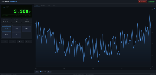
We made a specific call on the host-side software: no drivers, no installers, no account, no cloud. You open a web page, click Connect, you're talking to the card. That's the whole onboarding.
The app runs in Chrome or Edge and uses the Web Serial API to talk to the card over USB. Right now you get a big readout, a mode selector for V AC / V DC / A AC / A DC / Resistance, min/avg/max, a live chart, CSV export, and a serial console tab. The wire protocol is plain text at 115200 baud, MODE:VDC, READ, LOG:START. Nothing clever. Easy to script against if you want to hook the card into your own tools.
It's very much a work in progress. Next up: a real calibration flow, multi-channel views for when you have more than one card docked, annotated sessions, and a history browser that doesn't throw your data away when you close the tab.
The other piece we're excited about is mobile. The same ESP32-S3R8 that talks to the browser over USB also has BLE, so the plan is a phone app that pairs over Bluetooth and gets live readings with the card not plugged into anything on your end. Leave the dock on the bench, walk over to whatever you're measuring, start a reading from your phone. The radio is already on the board. The firmware already drives it. What's left is the client side.
Both apps will be free and open source. The card never talks to a cloud, you never make an account, and nothing you measure ever leaves your own machines.
What the review process keeps catching
We're building in public, so here's the honest version. It started as an RP2040-based wired-only meter. Then we wanted wireless, pivoted to the ESP32-S3R8, and had to rebuild the supply, decoupling, flash topology, and antenna keep-out around the new chip. After that we prototyped the card as a pure wireless receiver with the AFEs on a remote probe, decided that simplified the wrong things, and pulled the AFEs back on board.
Every serious review on this card finds something. The first flagged eighteen items. The second, after cleanup, four. The third, which we just ran this week, caught two more that slipped in during the last re-architecture. Spreadsheets and nitpicking, but it's the only reason the first PoC has any chance of coming back from fab in one working piece.
What's next
The first PoC batch is on the way. Once boards are in hand: mechanical fit against real tolerances, hipot across the isolation barrier, calibration against a reference, RF range inside the enclosure, and a subjective test of how the banana jacks actually feel under a probe.
If it survives all that, it opens up a modular Tool Card category inside the Framework ecosystem, power supply next, then logic analyzer, GPIO/UART breakout, oscilloscope module. Each one a card you keep docked, not a box you clear shelf space for.
What the community is telling us
We're at close to 1050 signups on hwlab.io/dockframe, and Tool Cards are a real chunk of the feedback. One subscriber described the multimeter + power supply combo as "a space saving modular development aid, easily pull power for microcontrollers with a nice multimeter for in-circuit sanity checks", honestly a better one-line pitch than anything we've written ourselves. We've also had requests for logic analyzers, GPIO and UART breakouts, an oscilloscope module, an SWR analyzer for RF work, and one person who wants to plug it into classic car sensors for temperature and oil pressure.
A Tool Card that lives in a dock you already own sits in a different category than a bench instrument. It changes the question from "do I need a multimeter badly enough to give it shelf space" to "do I want it in slot two today." If you have ideas, tell us here.
Why this matters
Designing for this form factor isn't "scaling down" anything. Component choice is dictated by volume. Isolation is a creepage-versus-clearance fight. Antenna placement is never ideal. Every decision is a compromise, and you don't find out who was right until the boards come back.
We want the Multimeter Card to be the kind of tool you leave docked. Reliable enough to trust, compact enough to forget about, good enough that you reach for it before the bench DMM for anything that isn't a certification measurement. That's the bar. The first PoC is the first real test of whether we hit it.
DockFrame is a modular USB-C hub for Framework laptop users, makers, and engineers. Open source hardware, open process. Follow us on GitHub, join the Discord, or tell us what you want to see.
Support Us on Crowd Supply
We’re on Crowd Supply, and we need your help to bring DockFrame to more people. Your backing makes it possible to keep prices low and quality high, so everyone can enjoy the power of an open-source modular USB Hub ecosystem.
Check out the campaign and get involved: DockFrame on Crowd Supply

